StarLine i95 LUX, i95, i95 ECO
EN version mock manual
- User manual
- Safety Measures for Operating the Immobilizer
- General Description
- Technical Specifications
- Table of possible indications
- Control via Tag
- Control via Indication Module
- Operation Modes and Functions
- Emergency Unlock Mode
- Changing the unlock code
- Device registration mode
- Setup Recommendations
- Installiation manual
- Table of possible indications
- Delivery set
- Technical Specifications
- Connection diagram
- General Installation Requirements
- Immobilizer Connection
- Telematic setting of the immobilizer
- Programming Parameters with the Tag
- Registration of new devices
- Installation sheet
- Software
User manual
Safety Measures for Operating the Immobilizer
Please read carefully!
Some simple requirements must be observed for safe use of the immobilizer:
1. The immobilizer shall be installed only by qualified specialists. The immobilizer is connected to the car circuits related to engine operation. A radio channel is used for data exchange in the system, therefore stable tag identification depends on correct arrangement of the immobilizer components.
2. If you hear a sound signal, warning about blocking, during car driving, – immediately take actions for safe stop. Engine blocking may cause increase of the force necessary for steering wheel turning and the force of brake pedal pressing. It is extremely dangerous, particularly at high-speed driving.
3. If you hear a signal, warning about discharge of the tag battery, take timely actions to replace the battery. It is recommended to have a new battery in the car, keeping its factory packing.
4. Do as follows to use the car on which the immobilizer is installed:
• carry along the tag
• know the unlocking code
The transport vehicle cannot be drove in case of tag loss and absence of the unlocking code!
General Description
The StarLine i95 LUX, i95, and i95 ECO immobilizers are designed to protect the vehicle from theft and hijacking (hereinafter referred to as the immobilizer). Protection is provided by engine blocking. Data exchange between system components is carried out via radio channel (in the frequency range of 2.4 GHz) using encryption resistant to intellectual hacking.
Key Features
- Protection against theft and hijacking.
- Automatic owner recognition.
- Secure radio channel.
- Built-in motion sensor.
- Control of hood (door) lock.
- Waterproof tag.
- Universal connection channel.
- Configuration via the StarLine Master application.
Plastic card
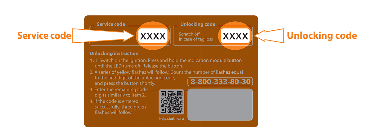
The immobilizer delivery set includes a plastic card containing the following data:
- Service code — It is intended for setting and programming of immobilizer parameters. The service code is provided in the open form.
- Unlocking code — Allows for driving the car in case of batterydischarge or tag loss. The unlocking code is hidden under a scratch strip.
Do not tell the unlocking code to anyone! Remember that a malefactor, knowing the personal code, may deactivate the immobilizer’s protective functions. If you have grounds to think that the unlocking code became known to third parties, change it as soon as possible.
You should carry along the plastic card or note down the unlocking code in an accessible place (for instance, in the mobile telephone).
Technical Specifications
Blocking module
| Parameter | Value |
|---|---|
| Frequency range of control radio signals, GHz | 2.4 |
| Type of control code | dialogue |
| Maximum coverage range | up to 10 meters (*) |
| Ingress Protection | IP67 |
| Supply Voltage, V | 9–16 |
| Consumption current with switched-off ignition, mA |
|
| Consumption current with switched-on ignition, mA | 6.8 (**) |
| Maximum current load via relay contacts, A | 10 |
| Maximum current load at hood lock outputs, A | 20 |
| Operating temperature range, °С | from −40 to +125 |
(**) — with engine blocking inactive
Indication module
| Parameter | Value |
|---|---|
| Frequency range of control radio signals, GHz | 2.4 |
| Type of control code | dialogue |
| Maximum coverage range | up to 10 meters (*) |
| Ingress Protection | IP67 |
| Supply Voltage, V | 9–16 |
| Consumption current with switched-off ignition, mA | 0.01 |
| Operating temperature range, °С | from −40 to +85 |
(*) — depends on location of the immobilizer components
Tag
| Parameter | Value |
|---|---|
| Frequency range of control radio signals, GHz | 2.4 |
| Type of control code | dialogue |
| Maximum coverage range | up to 10 meters (*) |
| Ingress Protection | IP67 |
| Supply Voltage, V | 3.3 |
| Operating temperature range, °С | from −20 to +70 |
| Battery type | CR2025, CR2032 |
| Battery life time | up to 12 months |
(*) — depends on location of the immobilizer components
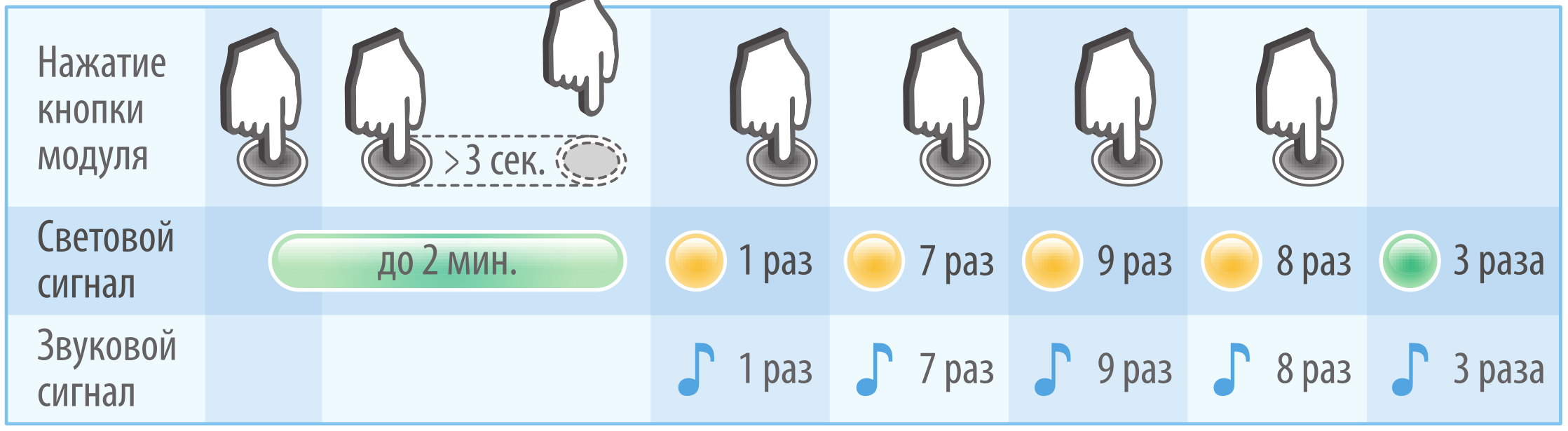
Table of possible indications
|
Event |
Tag (LED) |
Sound indication |
Notes |
| Warning of upcoming engine blocking | — |
intermittent sound signals |
Take action to stop the car |
|
Discharged tag battery |
 |
3 sound signals |
Install new battery |
|
Normal security mode |
 |
— |
If the LED flashes once at button pressing, the tag is outside the coverage range. Security functions are disabled in the service mode.
|
|
Antihijack mode |
 |
— | |
|
Service mode |
 |
— | |
| Successful tag authorization | — |
1 sound signal |
|
| Tag is absent. Prompt to enter the unlocking code | — | long sound signal | For immobilizers i95 ECO, i95. |
| Normal mode. Tag is absent | — |
1 sound signal every 2 minutes |
If the tag was lost after motion start (in the normal security mode) |
| Failure of the hood lock circuit | — | 2 sound signals | Fix hood lock circuit |
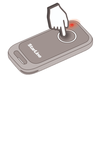
Control via Tag

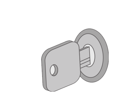
The tag serves as an electronic key. When traveling in a vehicle equipped with an immobilizer, it is necessary to always have the tag with you. Exchange of codes via radio channel between the tag and the locking module prevents engine locking during the journey. If an attempt is made to drive the vehicle without the tag, the engine will be locked.
It is recommended to carry the tag separately from the main keychain. Do not leave the tag in the car - in this case, the protective functions of the immobilizer will be disabled.
МThe tag has a button and a tricolor LED indicator, which are used for:
- Displaying the current operating mode.
- Monitoring the communication between the tag and the locking module.
- Switching between security modes.
- Entering the service mode.
The tags included in the immobilizer kit are initially in transport mode, in which they are disabled! Pressing the tag button in this mode will be indicated by green and red flashes of the built-in LED.
Before starting operation, it is necessary to press the tag button several times until the color of the flashes changes to green.
Up to four tags can be registered in the immobilizer, and all tags can be inside the car simultaneously.
Checking the Operating Mode and Communication Control
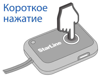
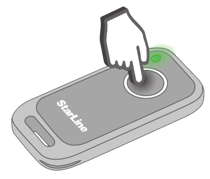
- Briefly press the tag button.
- The tag LED will flash 1 or 2 times. The flash color will correspond to the current operating mode of the immobilizer.

- The second LED flash indicates the presence of stable communication between the tag and the locking module.
If the second flash is absent, the communication between the tag and the locking module is disrupted. This may occur when moving away from the vehicle at a distance of more than 10 meters or in the presence of strong interference.
In the i95 ECO, when the ignition is off, there is no communication between the tag and the locking module.
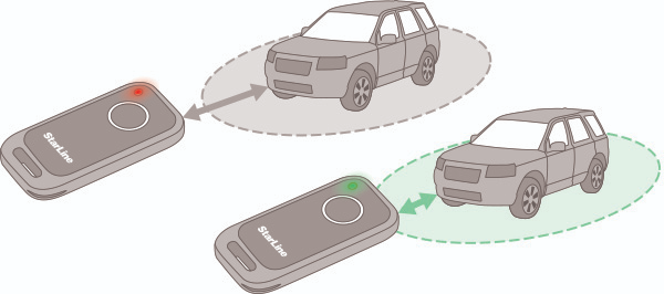
Choosing the Security Mode
To change the security mode, follow these steps:
- Press and hold the tag button.
Immediately after pressing, the tag will indicate the current operating mode and the status of the communication with the locking module. If the button is held for more than 2 seconds, the LED will light up for 2 seconds. The flash color will correspond to the next security mode. - Release the tag button during the 2-second period indicating the next security mode.
- Successful mode change will be confirmed by a flash of the LED, the color of which will correspond to the new operating mode.
Example of transitioning from normal mode to antihijack mode:

Transition between security modes can be performed even if there is no communication between the tag and the locking module (when away from the vehicle). The selected mode will be set after the first successful exchange of codes between the tag and the immobilizer.
Low Battery Alert for Tag
To prevent engine locking in case of tag battery discharge, the immobilizer monitors its charge level.
A low battery level in the tag is indicated by three short audible signals within 5 minutes after turning on the ignition.
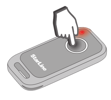
Additionally, battery discharge is indicated by three flashes of red color when pressing the tag button.

Complete battery discharge will result in tag deactivation. In this case, the engine will be locked. When the battery discharge indication appears, it is necessary to replace the battery as soon as possible.
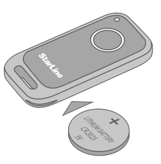
Battery Replacement
The tag uses one CR2025 or CR2032 type battery. The battery life is up to 12 months and depends on the quality of the battery and the immobilizer settings.
To replace the battery, carefully use a flat metal or plastic object (metal ruler, thin plastic) to open the tag housing and, observing the polarity (as shown in the photo), install the battery into the compartment. Before closing the tag housing, place a waterproof seal between its parts. After installing the battery in the tag, the immobilizer is ready for use.

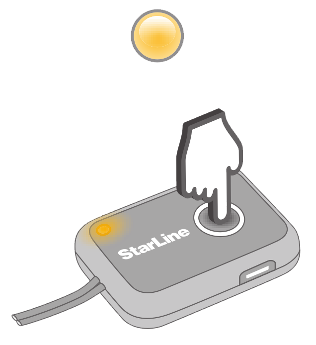
Control via Indication Module
The indication module is installed inside the vehicle. The main purpose of the indication module is to provide advance warning of an impending engine lockout, which may occur due to the absence of the tag or its battery being fully discharged.
Additionally, the indication module:
- Displays the current operating mode.
- Shows the number of tags registered in the locking module.
- Indicates the discharge of the tag battery.
- Is used for entering the unlock code.
- Allows access to the "Programming" and "Device Registration" modes.
Only one indication module can be registered in the immobilizer.
Communication Control
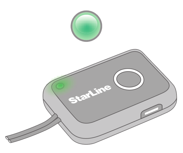
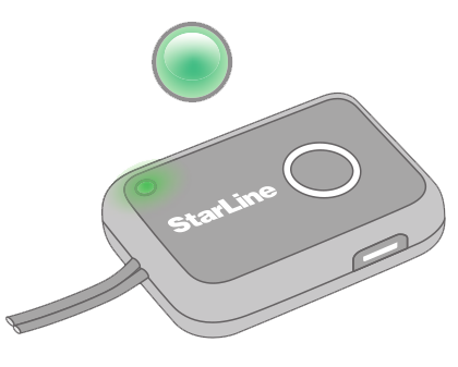
- Turn on the ignition. The indication module will establish communication with the locking module (within 10 seconds). This procedure will be indicated by green flashes of the LED on the indication module.
- After establishing communication with the locking module, the LED will stay lit for 2 minutes. During this time, the color of the LED will indicate the operating mode.

If communication with the locking module fails (for example, due to high levels of interference), the indication module will issue a warning with a red flash of the LED and an audible signal.
Subsequently, the LED on the indication module will flash red every minute until the ignition is turned off or until the locking module is within radio communication range. If communication with the locking module is lost some time after turning on the ignition, no warning signals will be issued.
Checking Operating Mode
Briefly press the indication module button. The LED on the module will stay lit for 2 minutes. The color of the indication will correspond to the current operating mode of the immobilizer.

Checking the Number of Registered Devices
- Briefly press the indication module button. The LED on the module will stay lit for 2 minutes.
- During the two-minute indication, press the button again briefly - the LED will go out for a short time. Then flashes of green color will follow, the number of which will be equal to the number of registered tags.

Operation Modes and Functions
The immobilizer is a system for engine start access with protection and service functions.

For driving a vehicle equipped with the immobilizer, it is sufficient to have the tag with you. After the tag appears within the range of the locking module, automatic code exchange occurs between them via radio communication. The vehicle protection is provided by engine locking when attempting to move the vehicle without communication with the tag.
Locking is activated only if the vehicle is in motion with the engine running (ignition on). If the tag is absent in the reception area and the engine is running but the vehicle is stationary, locking is not activated. This allows the immobilizer to be used in conjunction with any automatic and remote engine start systems.
The immobilizer has the following structure of operating modes:
| Security Modes |
Normal mode |
| «Antihijack» | |
| Additional Modes |
Service mode |
| «Emergency unlock» | |
| «Telematic configuration» | |
| «Programming» | |
| «Device registration» |
Security modes provide protection against theft (normal mode) and protection against armed robbery («Antihijack»).
Additional modes are intended for servicing and configuring the immobilizer (service mode, telematic configuration mode, and parameter programming mode), disabling security functions in case of battery discharge, loss of the tag (emergency unlock mode), as well as registering new components in the system (device registration mode).
The main differences between the modes are summarized in the table.
| Parameter | Security Modes | Additional Modes | |||||||||
| Normal | Anti-hijack | Service mode | Telematic configuration | Emergency unlock | Programming | Device registration | |||||
|
Color Indication (Tag, Indication Module) |
|
|
|
— | — | — | — | ||||
| Entry into mode | using tag | using PC |
using ignition key (i95 ECO, i95) using indication module button (i95 LUX) |
||||||||
| Exit from mode | using tag | using PC | upon tag appearance | upon ignition switch off | |||||||
| Block activation | permitted | prohibited | permitted | prohibited | |||||||
Normal Mode
In normal mode, after the ignition is turned on, the tag should remain inside the vehicle until the first successful data exchange. Subsequently, the presence or absence of the tag does not affect the operation of the immobilizer — the engine will not be locked until the next ignition switch on. The presence of the tag is monitored in the background: if communication with the tag is interrupted (for example, if it is left in the garage), periodic audible signals about the absence of the tag will be emitted.
«Antihijack» Mode
In "Antihijack" mode, the immobilizer constantly checks for the presence of the tag inside the vehicle. If the tag disappears from the area of action while driving, an audible warning about the impending lockout will start, and 20 seconds later the engine will be locked. If the tag is absent from the moment the ignition is turned on, the lockout will occur when starting to move.
Automatic data exchange between the tag and the immobilizer prevents engine locking after tag recognition for 40, 60, or 120 seconds depending on the settings made.
If brake pedal polling is used in the system, engine locking when the tag is lost in "Antihijack" mode will occur after pressing the brake pedal. If the brake pedal was not pressed, the lockout will occur after a double set time interval.
For the "Antihijack" mode to work, engine locking while driving must be enabled in the settings. Otherwise, the engine will be locked when the ignition is turned on.
Engine Blocking
Upon detecting the tag within the reception area after ignition is turned on, a short audible signal is emitted (unless otherwise specified by settings). If by the time the vehicle starts moving, communication session hasn't occurred (either due to tag absence or tag battery depletion), audible signals indicating imminent blocking (depending on the selected security mode and settings) are activated, and engine blocking commences.
If you hear the audible indication of imminent blocking, take immediate measures to safely stop the vehicle!
Engine blocking is activated for 20 seconds. If the vehicle starts moving after the blocking cycle ends, the blockage will be reactivated for another 20 seconds. Each attempt to move the vehicle with the ignition on will result in engine blocking. If blocking occurs 3 times consecutively, the engine will be blocked until the tag reappears.
If intermittent blocking algorithm is set in the settings, engine malfunction simulation occurs — the blocked circuit periodically breaks and restores according to the following algorithm:
| Blocking stages | Blocked | pause | Blocked | pause | Blocked | pause | Blocked |
| Duration, seconds | 2 | 2 | 3 | 2 | 5 | 2 | 20 |
Driving the vehicle will become possible when:
- the tag appears within the reception area of the locking module;
- emergency unlocking is performed using the unlock code.
Service Mode
A special mode is provided for servicing the vehicle, in which security functions are disabled. In service mode, the engine is not blocked, and lock control is disabled, regardless of the presence or absence of the tag.
Transitioning the immobilizer to service mode is only possible when the vehicle is within the tag's range.
- Press and hold the tag button. Immediately after pressing, the tag will indicate the current mode of operation and the communication status with the locking module. Then a 2-second indication of the next security mode will be performed. Hold the button for more than 7 seconds — until the LED turns yellow, indicating the possibility of transitioning to service mode.
- Release the tag button during the 2-second yellow LED illumination.
- Transition to service mode will be confirmed by two flashes of the yellow LED.
Example transition to service mode:

If all tags registered in the immobilizer are lost, exiting the service mode will be impossible.
To exit the service mode, perform the security mode change procedure (press and hold the button until the LED indicates the security mode color, then release the button during the 2-second flash). The immobilizer will return to security mode. It is recommended to test the operation in one of the security modes and ensure that the engine is blocked when attempting to drive the vehicle without a tag.
In service mode, the security functions of the immobilizer are disabled. Use this mode only to transfer the vehicle for service.
«Hands-Free» Mode

Door lock control is possible only for the i95 and i95 LUX immobilizers.
If "Hands-Free" mode is enabled in the settings, the immobilizer will remotely control the door lock according to the algorithm below.
The "open" pulse will be issued:
-
when the tag approaches the stationary vehicle to a distance corresponding to the proximity threshold;
-
when the ignition is turned off, if the "Unlocking upon ignition off" option is enabled;
-
when switching to emergency unlock mode (after entering the unlock code);
-
when switching to service mode.
The "close" pulse will be issued:
- when the tag moves away from the stationary vehicle to a distance corresponding to the departure threshold. The departure threshold is automatically calculated based on the proximity threshold value set in the door lock control range settings;
- when starting to move, if the "Additional locking upon movement start" option is enabled.
The "open" pulse will be issued only if the door locking was performed by the immobilizer, and vice versa. If door lock control was performed by any other means (not by the immobilizer), the "open" and "close" pulses will be absent.
When using the universal EXT channel connected to the hand touch sensor, the immobilizer will control the door lock according to the algorithm described below.
The "open" pulse will be issued:
- when the hand touch sensor is triggered in the presence of the tag;
- when the ignition is turned off, if the "Unlocking upon ignition off" option is enabled;
- when switching to emergency unlock mode (after entering the unlock code);
- when switching to service mode.
The "close" pulse will be issued:
- when the hand touch sensor is pressed for a long time (more than 3 seconds) or when the tag moves away;
- when starting to move, if the "Additional locking upon movement start" option is enabled.
In service mode, door lock control is disabled.
«Hood Lock Control»

If the "Hands-Free" mode is disabled in the settings, the immobilizer will remotely control the hood lock using one of the selected algorithms.
Hood Lock Control Based on Ignition Status
The "open hood" pulse will be issued:
- when the ignition is turned on in the presence of the tag;
- when switching to emergency unlock mode (after entering the unlock code);
- when switching to service mode.
The "close hood" pulse will be issued:
- after the tag moves away with the ignition off;
- when issuing audible warnings indicating an impending engine block.
For the i95 ECO immobilizer, the hood will be locked 10 seconds after the ignition is turned off.
Hood Lock Control Based on Tag Presence
The "open hood" pulse will be issued:
- when the tag approaches the stationary vehicle to a distance corresponding to the proximity threshold;
- when switching to emergency unlock mode (after entering the unlock code);
- when switching to service mode.
The "close hood" pulse will be issued:
- after the tag moves away from the stationary vehicle to a distance corresponding to the departure threshold;
- when issuing audible warnings indicating an impending engine block.
In service mode, hood lock control is disabled.
Emergency Unlock Mode
The "Emergency Unlock" mode is intended for emergency engine unlocking in case of battery discharge or loss of tags. In this mode, the system's protective functions are disabled until a tag appears within the radio channel's range.
Telematics Configuration Mode
The "Telematics Configuration" mode is designed for convenient and quick configuration of the immobilizer using the StarLine Master application.
Programming Mode
The "Programming" mode is intended for changing the unlock code, checking the stability of communication between the tag and the locking module, and adjusting the immobilizer's operation parameters using the tag. Entering programming mode is possible using either the unlock code or the service code. In the latter case, the option to change the unlock code will be unavailable.
Device Registration Mode
The "Device Registration" mode is intended for registering new components (tags, indicator modules) in the immobilizer's memory.
Emergency Unlock Mode
Entering this mode is done using the unlock code. The unlock code is located beneath the protective layer of the plastic card included in the package. It consists of four digits from 1 to 9 inclusively and can be changed by the user.
If the unlock code is entered incorrectly, a "long" signal will sound. If the code is entered incorrectly 5 times within 30 minutes, the input procedure will be blocked for 15 minutes. The prohibition on entering the code is lifted when a tag appears.
When switching to "Emergency Unlock" mode, the locking module issues a pulse to open the hood or doors.
In "Emergency Unlock" mode, the engine is not blocked. Exiting this mode occurs automatically when a tag appears within the range. Turning off the ignition does not exit the "Emergency Unlock" mode.
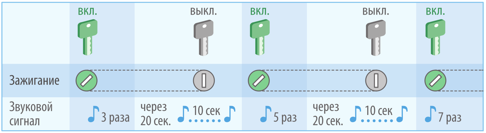
Unlocking via Ignition for i95 ECO, i95 Immobilizers
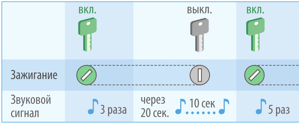
- Turn on the ignition.

- Wait for the start of the sound signal (if no tags are present) and turn off the ignition.

- Turn on the ignition - a series of sound signals will follow.
- Count the number of signals equal to the first digit of the unlock code and turn off the ignition.

- Enter the remaining digits of the unlock code following steps 3-4.
- Turn on the ignition.
If the unlock code is entered correctly, 3 short sound signals will follow.

The immobilizer will switch to "Emergency Unlock" mode.
Example of entering the unlock code 1798 using the ignition:
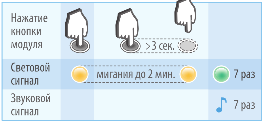
Unlocking via Indicator Module for i95 LUX Immobilizer
- Turn on the ignition
- Press and hold the indicator module button for more than 3 seconds - until the LED goes out. Release the button.

- Yellow flashes will follow, accompanied by sound signals. Count the number of flashes equal to the first digit of the unlock code and briefly press the indicator module button. The entry of the first digit is complete.

- Enter the remaining digits of the unlock code following step 3.
- If the code is entered correctly, 3 short sound signals will follow, accompanied by green LED flashes.

The immobilizer will switch to "Emergency Unlock" mode
Example of entering the unlock code 1798 using the indicator module:
Changing the unlock code
To change the code to a new one, you need to know the current unlock code.
Changing the unlock code requires entering the "Programming" mode.
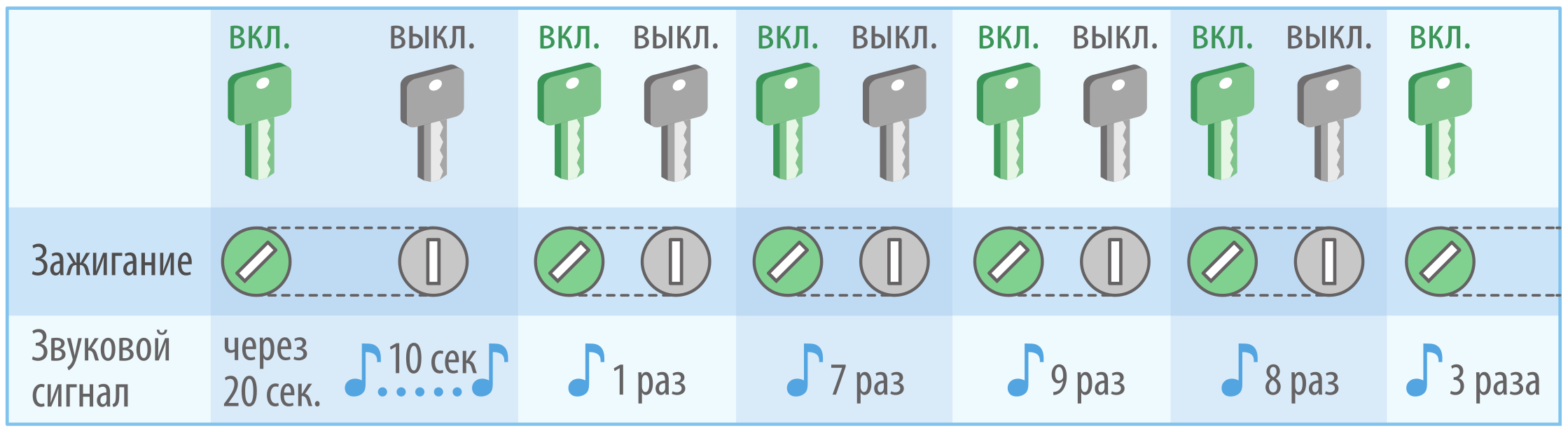
Entering the "Programming" mode for i95 ECO and i95 Immobilizers:
- Switch the immobilizer to "Emergency Unlock" mode and leave the ignition on.
- After 20 seconds, a long (10-second) signal will sound. Turn off the ignition during the long signal.
- Turn on the ignition. There will be 5 short confirmation sound signals.
The immobilizer will enter the "Programming" mode.
Example of entering the "Programming" mode using the unlock code 1798 for i95 ECO, i95 Immobilizers
- Switch the immobilizer to "Emergency Unlock" mode.

- Switch the immobilizer to "Programming" mode.


Entering "Programming" mode for i95 LUX Immobilizer
- Switch the immobilizer to "Emergency Unlock" mode and leave the ignition on.
- Press the button on the indicator module briefly.

The LED will start flashing yellow. - Within the next 2 minutes, press and hold the button on the indicator module for more than 3 seconds until the LED goes out.

- Release the button. There will be 5 short signals with the green LED flashing.

The immobilizer will enter the "Programming" mode.

Example of entering the "Programming" mode using the unlock code 1798 for i95 LUX Immobilizer
- Switch the immobilizer to "Emergency Unlock" mode.

- Switch the immobilizer to "Programming" mode.

Changing the unlock code
To change the unlock code after switching the immobilizer to "Programming" mode, follow these steps:
- Remove the power source from the tag.

- Insert the power source into the tag.

- After a few seconds, the LED on the tag will start flashing green, indicating parameter input.

-
Press the button on the tag once when the LED is lit.

After the LED stops flashing, there will be a short green flash, after that the LED will turn red. -
While the LED is lit press the button the number of times corresponding to the first digit of the new unlock code (from 1 to 9).

A series of red flashes will follow, the number of which will correspond to the button press. After a short pause the LED will light up again. - Enter the remaining digits of the new unlock code following step 5.
- Successful change of the unlock code will be confirmed by a series of sound signals corresponding to its new value: the number of signals in the first series will correspond to the 1st digit, the second series to the 2nd digit, the third series to the 3rd digit, and the fourth series to the 4th digit of the new code.

The immobilizer will remain in "Programming" mode until the ignition is turned off.
Example of entering a new unlock code 5678 using the tag
Device registration mode
For registration of new components the immobilizer should be set to the device registration mode
Switchover to the registration mode from the service mode is impossible
To prevent unauthorized tag registration, entry in the device registration mode is possible only after entry of the unlocking code (given on the plastic card). If you have told the unlocking code to the installation specialist, change it after completion of device registration.
Data exchange via the radio channel during registration is unencrypted. Registration should be performed in an open space far away from possible signal interception areas.
Device Registration Mode Entry for Immobilizers i95 ECO and i95
- Switch the immobilizer to "Emergency Unlock" mode and leave the ignition on.
- After 20 seconds, a long signal (10 seconds) will sound. Turn off the ignition during this long signal.
- Turn on the ignition. Five short confirmation beeps will follow.
The immobilizer will enter "Programming" mode. - After 20 seconds, a long signal (10 seconds) will sound. Turn off the ignition during this long signal.
- Turn on the ignition. Seven short confirmation beeps will follow.

The immobilizer will enter "Device Registration" mode.
The immobilizer will remain in programming mode until the ignition is turned off.
Example of entering "Device Registration" mode using the unlock code 1798 for immobilizers i95 ECO and i95
- Switch the immobilizer to "Emergency Unlock" mode.

- Switch the immobilizer to "Programming" mode, then to "Device Registration" mode.

Device Registration Mode Entry for Immobilizer i95 LUX
- Switch the immobilizer to "Emergency Unlock" mode and leave the ignition on.
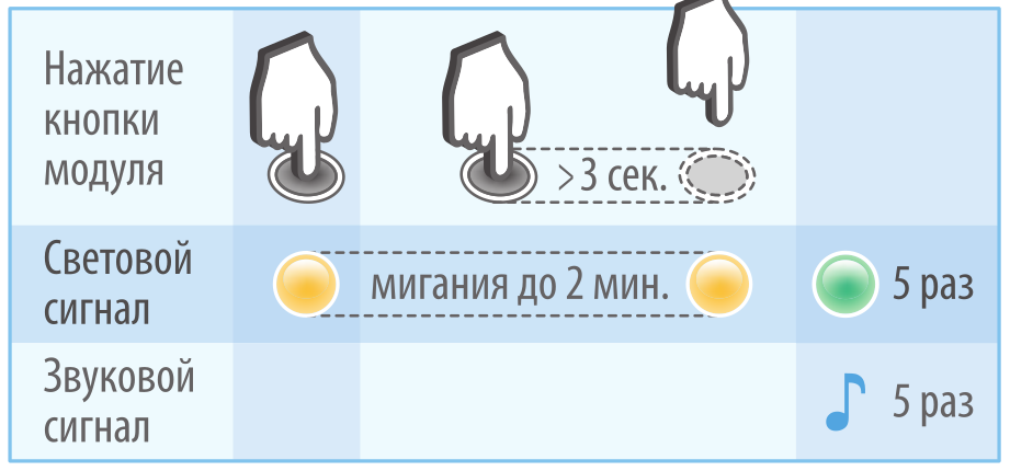
- Briefly press the button on the indicator module.
The LED will start flashing yellow. - Within the next 2 minutes, press and hold the button on the indicator module for more than 3 seconds until the LED goes out.
- Release the button. Five short beeps will follow, with the green LED flashing.
The immobilizer will enter "Programming" mode. - Briefly press the button on the indicator module.
The LED will start flashing yellow. - Within the next 2 minutes, press and hold the button on the indicator module for more than 3 seconds until the LED goes out.
- Release the button. Seven short beeps will follow, with the green LED flashing.
The immobilizer will enter "Device Registration" mode.
The immobilizer will remain in programming mode until the ignition is turned off.
Example of entering "Device Registration" mode using the unlock code 1798 for the i95 LUX immobilizer
- Switch the immobilizer to "Emergency Unlock" mode using the current code—1798.

- Switch the immobilizer to "Programming" mode.

- Switch the immobilizer to "Device Registration" mode.

Tag Registration
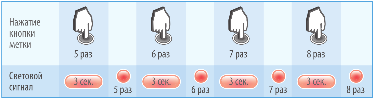
To register tags after switching the immobilizer to "Device Registration" mode, perform the following steps:
- Remove the battery from the tag.
- Press and hold the button on the tag, then insert the battery back into the tag.

- Keep the tag button pressed for at least three seconds, then release it.
- Successful tag registration will be confirmed by green LED flashes. The number of flashes will correspond to the total number of registered tags. In case of a registration error (e.g., if the ignition is turned off before the sequence is complete), the LED will flash red.
- Remove the battery from the tag and reinstall it to restart the tag.
- Repeat steps 1-5 for all other tags to be registered.
- Turn off the ignition to exit "Device Registration" mode.
All necessary tags must be registered sequentially within one programming cycle. Registering the first tag will automatically erase information about all previously registered tags, preventing the use of lost or stolen tags by unauthorized individuals. The immobilizer supports registration of up to 4 tags.
Indicator Module Registration
To register the indicator module after switching the immobilizer to "Device Registration" mode, perform the following steps:
- Connect power to the indicator module.
- Wait for the communication check to complete (10 seconds until the LED stops flashing).
- Press and hold the button on the indicator module for at least 3 seconds, then release it.
- Successful registration of the indicator module will be confirmed by a green LED flash. In case of a registration error (e.g., if the blocking module is not in registration mode), the LED will flash red.
- Turn off the ignition to exit "Device Registration" mode.
The immobilizer supports only one indicator module.
Setup Recommendations
When visiting an installation center for the installation and configuration of the immobilizer, we recommend that you draw the installer’s attention to the programmable options designed to provide additional comfort and security during the use of the device.
Below are the main parameters of the immobilizer available for configuration:
- “Hands-Free” Mode (only for i95 and i95 LUX) – Used for automatically locking and unlocking the car doors when the owner with the tag approaches or moves away from the stationary vehicle.
-
Universal Channel Connection Mode – Determines the operating mode of the universal channel, which is intended for implementing one of the following options:
- Engine lock when the tag is lost in anti-hijack mode after pressing the brake pedal;
- Determining the status of door or hood limit switches;
- Unlocking the central door lock by the touch sensor signal on the door handle in “Hands-Free” mode (only for i95 and i95 LUX);
- Activating the brake lights to warn of the vehicle’s impending stop before the blocking algorithm begins;
- Indicating the locking and unlocking of doors using the parking lights.
-
Delay Before Blocking After Start of Movement – Sets the delay duration before blocking activation after the start of movement in the absence of a tag signal:
- No delay;
- 5 seconds;
- 10 seconds.
- Intermittent Blocking Algorithm – Allows simulating engine malfunction during blocking.
- Sound Indication – Enables or disables sound signals from the indicator module in the following cases:
- Tag detection when the ignition is turned on;
- Tag loss in normal mode;
- Blocking warning;
- Low battery indication of the tag.
- Light Indication (only for i95 LUX) – Enables or disables light signals from the indicator module in the following cases:
-
- Tag detection when the ignition is turned on;
- Blocking warning;
- Indication of the current operating mode;
- Low battery indication of the tag.
For detailed information on setting up the immobilizer, refer to the relevant sections of the installation instructions and the user manual.
Installiation manual
Table of possible indications
|
Event |
Tag (LED) |
Sound indication |
Notes |
| Warning of upcoming engine blocking | — |
intermittent sound signals |
Take action to stop the car |
|
Discharged tag battery |
|
3 sound signals |
Install new battery |
|
Normal security mode |
|
— |
If the LED flashes once at button pressing, the tag is outside the coverage range. Security functions are disabled in the service mode.
|
|
Antihijack mode |
|
— | |
|
Service mode |
|
— | |
| Successful tag authorization | — |
1 sound signal |
|
| Tag is absent. Prompt to enter the unlocking code | — | long sound signal | For immobilizers i95 ECO, i95. |
| Normal mode. Tag is absent | — |
1 sound signal every 2 minutes |
If the tag was lost after motion start (in the normal security mode) |
| Failure of the hood lock circuit | — | 2 sound signals | Fix hood lock circuit |
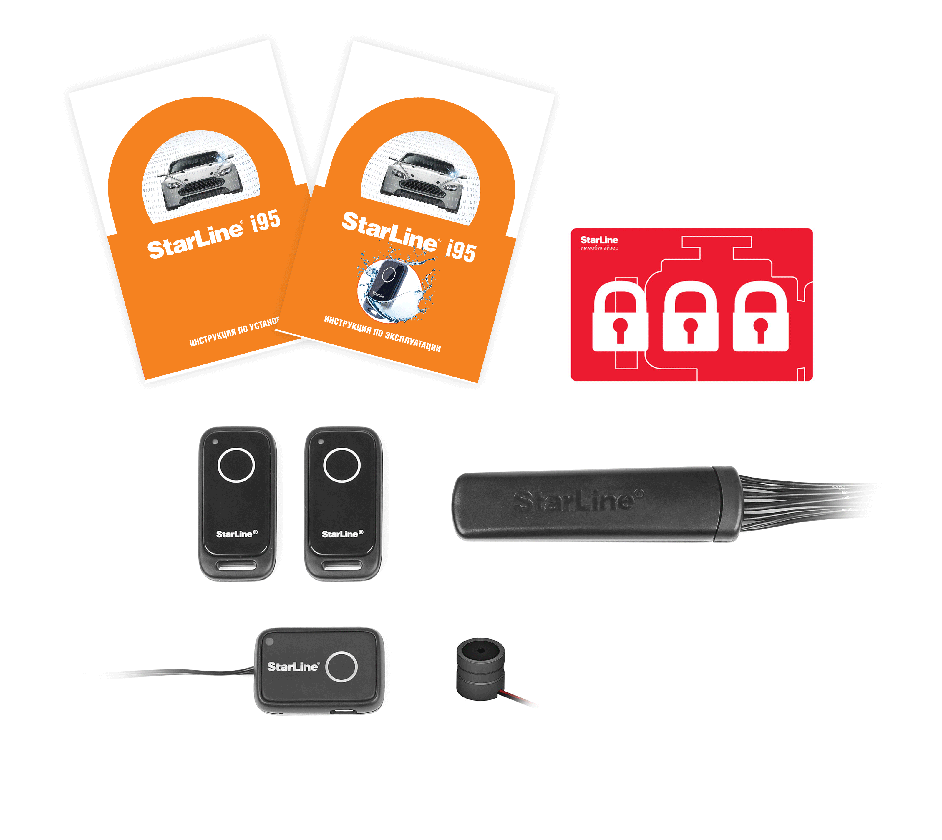
Delivery set
The differences between the kits and the delivery sets are presented in the table:
| № | Component | i95 ECO | i95 | i95 LUX |
|---|---|---|---|---|
| 1 | User manual | |||
| 2 | Installation manual | |||
| 3 | Plastic card | |||
| 4 | Tag with battery, 2 pcs. | |||
| 5 | Blocking module | |||
| 6 | Buzzer | |||
| 7 | Indication module | |||
| Function | i95 ECO | i95 | i95 LUX | |
| Central lock control (“Hands free” mode) | ||||
| Tag authorization output (status output) | ||||
Technical Specifications
Blocking module
| Parameter | Value |
|---|---|
| Frequency range of control radio signals, GHz | 2.4 |
| Type of control code | dialogue |
| Maximum coverage range | up to 10 meters (*) |
| Ingress Protection | IP67 |
| Supply Voltage, V | 9–16 |
| Consumption current with switched-off ignition, mA |
|
| Consumption current with switched-on ignition, mA | 6.8 (**) |
| Maximum current load via relay contacts, A | 10 |
| Maximum current load at hood lock outputs, A | 20 |
| Operating temperature range, °С | from −40 to +125 |
(**) — with engine blocking inactive
Indication module
| Parameter | Value |
|---|---|
| Frequency range of control radio signals, GHz | 2.4 |
| Type of control code | dialogue |
| Maximum coverage range | up to 10 meters (*) |
| Ingress Protection | IP67 |
| Supply Voltage, V | 9–16 |
| Consumption current with switched-off ignition, mA | 0.01 |
| Operating temperature range, °С | from −40 to +85 |
(*) — depends on location of the immobilizer components
Tag
| Parameter | Value |
|---|---|
| Frequency range of control radio signals, GHz | 2.4 |
| Type of control code | dialogue |
| Maximum coverage range | up to 10 meters (*) |
| Ingress Protection | IP67 |
| Supply Voltage, V | 3.3 |
| Operating temperature range, °С | from −20 to +70 |
| Battery type | CR2025, CR2032 |
| Battery life time | up to 12 months |
(*) — depends on location of the immobilizer components
Connection diagram
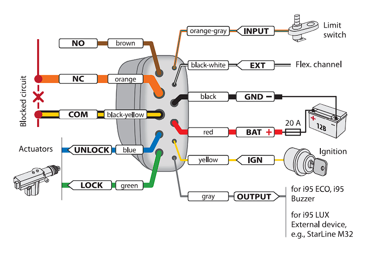
The device is supplied with text and color markings
Diagram of external outputs
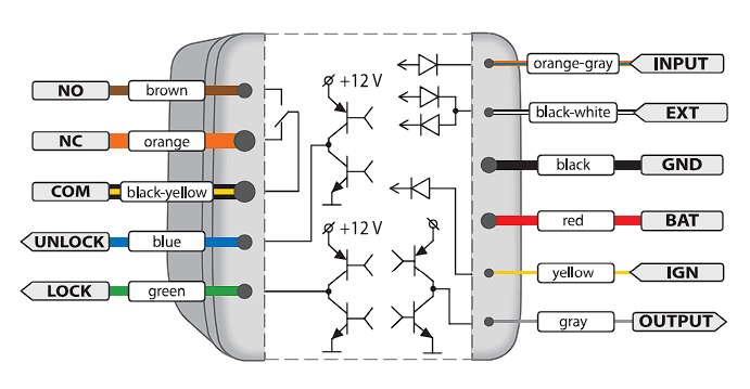
Designation of external outputs
All blocking module wires are marked white.
| Marking | Designation |
|---|---|
| GND | Ground (– |
| BAT | Power supply (+) |
| IGN | Ignition |
| NO | Normally open relay contact |
| NC | Normally closed relay contact |
| COM | Common relay contact |
| UNLOCK | Opening the door lock (or hood lock) |
| LOCK | Closing the door lock (or hood lock) |
| INPUT | Input the door (or hood) limit switch |
| OUTPUT | i95 ECO, i95 - buzzer output i95 LUX - status output |
| EXT | Flexible channel |
General Installation Requirements
-
The StarLine i95 ECO, i95, and i95 LUX immobilizers are designed for installation on vehicles and motorcycles with a 12V electrical system.
-
Before installing the immobilizer, ensure the vehicle's electrical circuits are functioning correctly and that there are no error indications from the vehicle’s standard equipment on the dashboard (e.g., "Check Engine," "Airbag," etc.).
-
Install the immobilizer in accordance with the installation diagram.
-
Route the wires as far as possible from sources of electrical interference, such as ignition coils, high-voltage wires, etc. Ensure that the wires do not come into contact with moving parts of the vehicle's structure, such as pedals, steering rods, etc.
Before beginning the installation, familiarize yourself with the operation principles and functional capabilities of the immobilizer as described in the User Manual.
After installing the immobilizer, complete the Installation Sheet in the Installation Instructions.
The tags included with the immobilizer are initially in transport mode, which means they are deactivated! Pressing the tag button in this mode will be indicated by green and red flashes of the built-in LED. Before use, press the tag button several times until the flash color changes to green.
Placement Recommendations
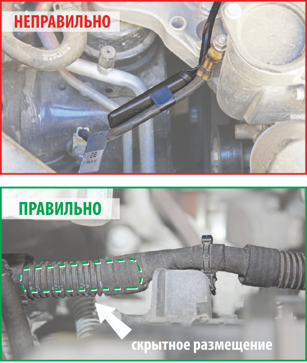
Place the blocking module discreetly in locations that are not accessible without partially disassembling elements of the body, engine, or interior. The blocking module can be placed either in the vehicle interior or in the engine compartment (under the hood), with precautions related to allowable temperature, environmental aggressiveness, and humidity.
To avoid interference with the radio channel, it is recommended to install the module as far as possible from metal parts of the vehicle, or to ensure a gap of a few centimeters from solid metal surfaces.
In shielding conditions, check the operating range of the radio channel. For the immobilizer to function properly, stable signal reception between the blocking module and the tag located at the driver's position is sufficient.
I95, I95 LUX
When using the “Hands-Free” mode (a programmable parameter), set the proximity threshold according to the desired door lock control range.
The blocking module can be installed in the vehicle's standard wiring harnesses for concealed placement. The harness must be stationary relative to the vehicle body.
Secure the module firmly to prevent false triggering of the motion sensor.
Immobilizer Connection
Power Connection
The GND wire of the blocking module must be connected to the vehicle body or a conductor reliably connected to the body. This wire should be connected first during installation.
Ensure the module receives power via the BAT terminal, and this power should not be interrupted under any circumstances. Ignoring this requirement can lead to immobilizer malfunctions, such as unintended activation of the anti-theft function, which can cause sudden changes in engine performance. The IGN wire must have a +12V potential when the ignition is on and the engine is running.
When connecting the BAT wire, remember that the maximum current consumption can reach 30A (during the pulse control of the locks).
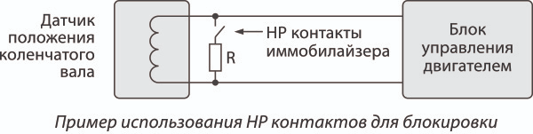
Engine blocking circuit connection
NO, NC and COM wires are connected to the circuit that needs to be blocked.
Both normally closed (COM and NC) and normally open (COM and NO) contacts can be used for blocking.
The relay activates only at the moment of engine blocking. Turning off the ignition does not trigger the relay.
The switching current should not exceed 10A continuously and no more than 20A for up to 1 minute (when switching circuits without an inductive load component). The size of the blocking module allows it to be installed close to the blocking point. Monitor the length and cross-section of the wires used for switching, as the switched current can be significant. If the current in the blocked circuit exceeds 10A, use an additional external relay.
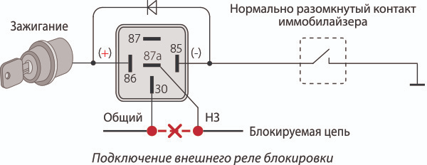
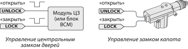
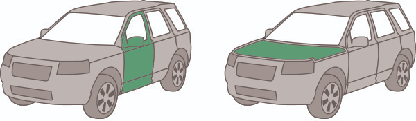
Lock Control Output Connection
UNLOCK and LOCK outputs are for controlling the hood lock or central door lock. They are designed with a power circuit (maximum output current 20A), so additional power modules are not required for lock control. Lock control can be implemented either through two-wire drive systems or by direct connection to the central locking system with negative control.
Connect the INPUT wire to the corresponding limit switch to allow the system to monitor the status of the doors or hood. If the door or hood is open, the lock will not be engaged. This wire should have a ground (–) when the hood (or doors) is open.
| Lock control method | Output | "Open" pulse | "Close" pulse | |
|---|---|---|---|---|
| Control of hood (disabled “Hands free” mode) | Two-wire locking system actuators | UNLOCK |
+ |
– |
| LOCK | – | + | ||
|
Control of doors (enabled “Hands free” mode) only for i95 LUX, i95
|
Central locking system with negative control | UNLOCK |
– |
break |
| LOCK | break | – | ||
| Two-wire locking system actuators | UNLOCK |
+ |
– |
|
| LOCK | – | + | ||
Before connecting the power outputs for the lock, choose the appropriate control scheme.
I95, I95 LUX
When connecting the immobilizer control outputs directly to the central door lock control unit, you must choose a central locking system with negative control. Failure to follow this rule can damage the equipment.
After connecting, be sure to check the locking and unlocking algorithm of the central locking system (CLS) with both the immobilizer and the vehicle key. In rare cases, incorrect CLS operation may occur due to the specific features of the vehicle's standard circuits. In such cases, use an additional external relay with dry contacts to connect to the CLS control inputs.
If a malfunction occurs in the lock control circuit (e.g., short circuit or overheating) when a pulse is issued to lock or unlock, there will be 2 short beeps. Fix the malfunction before using the system.
Connecting the buzzer (i95 ECO, i95)
Connect the OUTPUT wire to the negative (–) terminal of the buzzer, and the positive (+) terminal to the BAT wire of the blocking module (+12V circuit). A LED can be connected in parallel to the buzzer through a resistor with a resistance of 1-2 kΩ.
Place the buzzer so its signals are clearly audible from the driver's seat.
WARNING: Do not place the buzzer close to the blocking module, as this can trigger the motion sensor when sound signals are emitted.
Connecting the status output (i95 LUX)
The "status" OUTPUT allows the immobilizer to work with external devices (alarm system, monitoring system, etc.) to monitor the presence of the vehicle owner. The output works as follows:
- High-impedance state (open circuit) if the tag is distant or absent (signal level of the tag is below the set proximity threshold).
- Low potential (–) if the tag is near the vehicle (signal level of the tag exceeds the set proximity threshold).
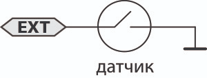
Connecting the Flexible Channel
The flexible channel (EXT) can be connected to one of the following inputs (outputs):
- Positive Brake Pedal Input: Used to implement brake pedal interrogation before starting the anti-hijack algorithm. Pressing the brake pedal is detected by the presence of +12V potential at the input.

- Positive Limit Switch Input: Used to determine the status of the doors or hood. This is for vehicles with +12V potential at the limit switch when the hood (doors) are open.

- Negative Touch Sensor Input (i95, i95 LUX): Connects to a touch sensor (installed separately). In "Hands-Free" mode, if the tag is in the blocking module’s action zone, the central lock will only unlock with a signal from the touch sensor. The door will lock with a long touch on the sensor (more than 3 seconds) or when the tag moves away.

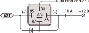
- Brake Light Output: Low-current (400 mA) negative output. Used to alert others of an impending vehicle stop before starting the engine blocking algorithm. Warning signals in the cabin are duplicated by flashing the vehicle's brake lights.

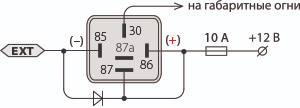
- Parking Light Output: Low-current (400 mA) negative output. Used for light indication of automatic lock and unlock. One signal is sent to the parking lights when issuing the "lock" pulse. Two signals are sent to the parking lights simultaneously with the "unlock" pulse.

- Status Output: Used as the default channel setting. Designed to monitor the presence of the tag near the vehicle. The output operation algorithm fully corresponds to the description in the "Connecting the Status Output" section. For the i95 ECO immobilizer, the status output works only when the ignition is on.

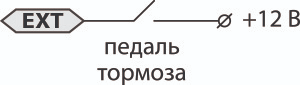
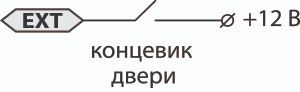

Before connecting the EXT wire, configure the channel according to the chosen connection method.
To attach the indicator module, use the double-sided tape included in the kit. If necessary, the power cord can be hidden in the cutout at the bottom of the indicator module housing.
Connecting the Indicator Module
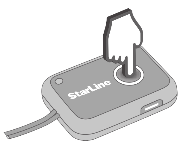
- Use the double-sided tape included in the kit to attach the indicator module to the selected surface.
- Ensure Ignition is Off.
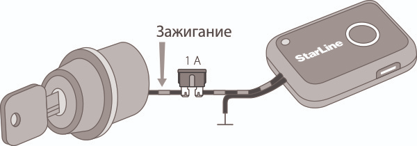
- Connect the black wire of the blocking module to the vehicle’s ground.
- Connect the black wire with a gray stripe to the standard wire that has +12V only when the ignition is on. The voltage should not disappear when the starter is engaged.
Telematic setting of the immobilizer
For quick and convenient setting of immobilizer parameters on a computer, download the special application «StarLine Master». Detailed information about configuring the immobilizer using the desktop application can be found in the manual in the "Help" section of the application.
Programming Parameters with the Tag
The programming mode is intended for configuring the parameters of the immobilizer.

Switching to programming mode from security mode requires entering the service code.
Switching to programming mode from service mode is not possible (indicated by yellow light).
For the i95 LUX immobilizer, enter programming mode using the indicator module. For the i95 ECO and i95 immobilizers, enter using the ignition key.
When entering programming mode using the service code, the option to change the unlock code will be unavailable.
Entering Programming Mode with the Service Code for i95 LUX
1. Turn on the ignition. Press and hold the indicator module button for more than 3 seconds until the LED goes off. Release the button.
2. Yellow flashes will follow, accompanied by beeps. Count the number of flashes equal to the first digit of the service code and briefly press the indicator module button. The first digit is entered.
3. Enter the remaining digits of the service code in the same manner as step 2.
4. If the service code is entered correctly, there will be 5 short beeps, and the system will enter programming mode. After a few seconds, the tag's LED will start flashing green every three seconds, waiting for parameter input.
If the service code is entered incorrectly, there will be 2 short beeps. If the code is entered incorrectly 5 times within 30 minutes, the entry procedure will be blocked for 15 minutes. The block will be removed when the tag is detected.
Example of entering the service code — 9567.
The immobilizer will remain in programming mode until the ignition is turned off.
Entering Programming Mode with the Service Code for i95 ECO, i95
1. Remove all tags from the immobilizer's range (or remove their batteries).
2. Turn on the ignition. Wait for the sound signal to start and then turn off the ignition.
3. Turn on the ignition again; a series of beeps will follow. Count the number of beeps equal to the first digit of the service code and turn off the ignition.
4. Enter the remaining digits of the service code in the same manner as step 3.
5. Turn on the ignition. If the service code is entered correctly, there will be 5 short beeps, and the system will enter programming mode.
If the service code is entered incorrectly, there will be 1 long beep. If the code is entered incorrectly 5 times within 30 minutes, the entry procedure will be blocked for 15 minutes. The block will be removed when the tag is detected.
6. Insert the battery into the tag. After a few seconds, the tag's LED will start flashing green every three seconds, waiting for parameter input.
Example of entering the service code — 9567.
The immobilizer will remain in programming mode until the ignition is turned off. Turning the ignition off and then back on will return the immobilizer to security mode.
Parameter Programming Table
When programming the immobilizer, you can refer to the following reference table. The number in the "Parameter" column corresponds to the number of times the tag button is pressed while the LED is green. The number in the "Value" column corresponds to the number of times the button is pressed while the LED is red.
Example of Setting a Parameter from the Programming Table
To set the low sensitivity level of the motion sensor, put the immobilizer into parameter programming mode. Then follow these steps:
1. Ensure that the tag's LED is flashing green every three seconds.
![]()
2. Press the tag button 9 times in succession while the LED is green. After the green LED stops flashing, there will be 9 short green flashes (corresponding to the number of presses). The LED will then change to red.
3. Press the tag button 3 times while the LED is red. After the red LED stops flashing, there will be a series of red flashes corresponding to the number of presses.
4. Successful setting of the low sensitivity level for the motion sensor will be confirmed by three beeps.
| Parameter | Value | Description | Note |
|---|---|---|---|
| 1 | Change of unlocking code | Available only when entering programming mode using an unlock code. It allows changing the 4-digit unlocking code, necessary for system switchover to the emergency unlocking mode |
|
| 1...9, 1...9, 1...9, 1...9 | Digits of new unlocking code | ||
| 2 | Option of tag coverage range testing | Activates the option of tag coverage range testing | |
| 1 | Option activation | ||
| 3 | Not used | ||
| 4 |
Blocking during driving | Allows engine blocking after driving start |
|
| 1 | On (default) | ||
| 2 | Off | ||
| 5 | Hands-Free mode |
Allows for switchover between automatic control of the central door lock and the hood lock.
|
|
| 1* |
Off, hood lock control according to tag’s presence. |
||
| 2 | Off, hood lock control according to ignition state. Two-wire drives to actuator (default) |
||
| 3* | On, door lock control. Central locking system with negative control |
||
| 4* | On, door lock control. Two-wire drives to actuator |
||
| 5 | Door lock control off | ||
| 6 | Door lock control |
Allows for selecting additional door lock control capabilities (used only together with Hands-Free mode). More detailed description is given in section “Door lock control” of User Manual. |
|
| 1 | No additional options (default) |
||
| 2* | Unlocking only | ||
| 3* | Additional locking at movement start, unlocking according to ignition switch-of | ||
| 7 | Tag coverage range | Allows to adjust the tag range for lock control | |
| 1 | Close range | ||
| 2 | Medium range (default) | ||
| 3 | Far range | ||
| 8 | Connection of the flexible channel |
Determines the operation algorithm of the flexible channel depending on the selected connection method.
|
|
| 1 |
Brake pedal |
||
| 2 |
Limit switch |
||
| 3* | Door handle sensor | ||
| 4 | Stop lights | ||
| 5 | Parking lights | ||
| 6** | Status output (default) | ||
| 9 | Movement sensor sensitivity | Allows to adjust movement sensor activation sensitivity | |
| 1 | High level | ||
| 2 | Medium level (default) | ||
| 3 | Low level | ||
| 10 | Delay before blocking after driving start | Allows for selecting the required duration of delay before blocking after driving start (in case of tag absence after ignition switch-on) |
|
| 1 | none (default) | ||
| 2 | 5 seconds | ||
| 3 | 10 seconds | ||
| 11 |
Delay before blocking in the Antihijack mode |
Allows for selecting the necessary delay duration after tag moving away (during driving) prior to blocking in the Antihijack mode |
|
| 1 | 40 seconds (deault) | ||
| 2 | 60 seconds | ||
| 3 | 120 seconds | ||
| 12 | Intermittent blocking algorithm | Allows and prohibits simulation of engine failure at blocking | |
| 1 | On | ||
| 2 | Off (default) | ||
| 13 | Common sound indication | Allows and prohibits all sound signals, except the warning signals in additional modes | |
| 1 | On (default) | ||
| 2 | Off | ||
| 14* | Common light indication |
Allows and prohibits light indication of tag detection and warning about upcoming blocking. |
|
| 1 | On (default) | ||
| 2 | Off | ||
| 15 | Tag detection signal | Allows and prohibits the signal of tag detection after ignition switch-on | |
| 1 | On (default) | ||
| 2 | Off | ||
| 16 | Signals of tag loss in the normal mode | Allows and prohibits the signals in case of tag loss in the normal mode | |
| 1 | On (default) | ||
| 2 | Off | ||
| 17 | Factory reset | Resets to default all programming table parameters | |
| 1 | Return to default settings | ||
| 18 | Delay prior to activate the motion sensor (after engine start) | Sets the necessary delay after remote engine start |
|
| 1 | 5 seconds (default) | ||
| 2 | 30 seconds | ||
| 3 | 60 seconds | ||
| 19 | Inversion of the “status output” of tag presence |
Allows setting the active level of the status output of tag presence (EXT). By default the output is “ground” if the tag is near. “Ground” can be set when the tag is outside the coverage range. | |
| 1 | On | ||
| 2 | Off (default) | ||
| 20 | Radio channel selection | Allows to select a radio channel for dialogue exchange, which does not interfere with the standard equipment of the car. | |
| 1...11 | Channel number | ||
Testing of coverage range
This option allows you to check the stability of the connection between the tag and the blocking module.
During the range and stability testing, a two-way radio exchange occurs every half second between the tag and the blocking module, indicated by a LED flash. A green flash corresponds to a successful exchange, while a red flash indicates a failed exchange. The testing session lasts for 10 minutes. After this period, the system will automatically return to the armed mode.
If the tag loses connection for more than three minutes, it will stop flashing until a successful exchange with the blocking module is established.
Stable connection is essential for the safe operation of the immobilizer and does not depend on the set lock control threshold.
Blocking While Driving
The immobilizer can block the engine at the start of movement. This allows the immobilizer to be used with remote engine start systems. If blocking while driving is disabled, the engine will be blocked when the ignition is turned on.
Hands-Free Mode Setup
i95, i95 LUX
Central lock control is only available for the i95 and i95 LUX immobilizers.
Door Lock or Hood Lock Control
The immobilizer has outputs for controlling the central door lock or the hood lock. Using the hands-free mode allows you to remotely control the central door lock as the tag approaches and moves away from the vehicle. For more details, see the "Door Lock Control" section in the User Manual.
The central lock control algorithm differs from the hood lock control. When setting up the immobilizer, you can choose one of these modes.
The system provides two ways to control the central door lock. If the pulse to open and close the lock is sent directly to the central lock, you need to use the control scheme for the central locking system with negative control. If the power contacts of the blocking module are connected to the door lock actuators, you should switch the system to control the two-wire drive of the locking system.
If the immobilizer's control outputs are directly connected to the central door lock, be sure to set up the control scheme for the central locking system with negative control. Failure to comply with this rule may result in equipment failure.
If a malfunction occurs in the actuator power circuit (e.g., short-circuit wires or overheating), two short beeps will sound when trying to send a pulse to open or close the lock.
Additional Door Lock Control (i95, i95 LUX)
The system provides additional door lock control in the hands-free mode. For more details, see the "Door Lock Control" section in the User Manual.
Setting the Tag Coverage Range
Distance between the tag and blocking module, at which the “open” pulse is issued, is set by three-level setting of coverage range (small, medium, large distance).
Distance and stability of tag communication with the blocking module is affected by many factors: interference, all kinds of
obstacles etc. Bear it in mind that the actual coverage range depends on tag location: if it is in the rear pocket or under thick clothes, coverage range is reduced. Moreover, the given distance is determined by the method of blocking module mounting in the underhood space – the deeper the device, the more difficult it is to find it, but the smaller the actual coverage range.
The maximum coverage range of the tag for the Hands-free mode is within 10 meters.
When the immobilizer is mounted in the passenger compartment, tag coverage range should be set to a small distance. In case of mounting in the underhood space – to a medium or large one.
Flexible Channel Setting
The EXT flexible channel can be connected to one of the following inputs (outputs):
- Positive brake pedal input. In antihijack mode, engine blocking will begin when the brake pedal is pressed, providing additional safety when stopping. If the brake pedal is not pressed, engine blocking will start after the doubled time interval set during the immobilizer parameter programming. Brake pedal pressing is detected by the appearance of a +12V potential at the input.
- Positive end switch input. Used to determine the state of the doors or hood for vehicles with positive end switches. When the doors or hood are open, a +12V potential is detected at the end switch.
- Negative touch sensor input (i95, i95 LUX). In hands-free mode, if the tag is within the blocking module's range, the central door lock will be unlocked only by the touch sensor signal (installed additionally). The door will lock after prolonged exposure to the sensor (more than 3 seconds) or as the tag moves away.
- Stop signal output. Low current (400 mA) negative output. Used to warn others of the vehicle's impending stop before initiating the engine blocking algorithm. Warning signals in the cabin are duplicated by the car's stop lights flashing.
- Parking light output. Low current (400 mA) negative output. Designed for light indication of automatic lock unlocking and locking. At the moment the "lock" pulse is issued, one signal is sent to the parking lights. Simultaneously with the "unlock" pulse, two signals are sent to the parking lights.
- Status output. Designed to monitor the presence of the tag near the vehicle. Used as the default channel setting.
Engine blocking setting
Movement Sensor Sensitivity
The initiation of the engine blocking algorithm depends on the three-level threshold adjustment of the movement sensor:
- High level: Reacts to movement initiation with a displacement of less than 10 meters in 10 seconds; generally triggers at speeds over 5 km/h with slow acceleration.
- Medium level: Reacts to movement initiation with a displacement of 10 to 20 meters in 10 seconds; generally triggers at speeds over 10 km/h with slow acceleration.
- Low level: Reacts to movement initiation with a displacement of more than 20 meters in 10 seconds; generally triggers at speeds over 30 km/h with slow acceleration.
Delay Before Activation of Engine Blocking After Movement Starts
The interval between the start of movement and the activation of engine blocking (10 or 5 seconds, as well as zero interval) is chosen based on the time required to reach the road where the hijacker can no longer discreetly attempt to disable the immobilizer. This delay can also be used for the safe activation of engine blocking after it starts.
Delay Before Activation of Engine Blocking in Antihijack Mode
The interval between the start of movement and the activation of engine blocking in antihijack mode (40, 60, or 120 seconds) is chosen based on the time required for the hijacker to drive away from the scene of the robbery.
Engine Blocking Algorithm
If the connection between the tag and the blocking module is not established at the time of vehicle movement, and the emergency unlocking procedure is not performed, the system will initiate engine blocking. The engine blocking procedure includes the possibility of simulating engine malfunction—the blocked circuit is periodically interrupted and restored according to the following algorithm:
| Blocking stages | Block | Pause | Block | Pause | Block | Pause | Block |
| Duration, seconds | 2 | 2 | 3 | 2 | 5 | 2 | 20 |
If the vehicle starts moving after the end of the blocking cycle, the blocking will be activated again for 20 seconds. If the blocking is triggered 3 times, the engine will remain blocked until the tag is detected.
Light and sound alarm setting
Common sound indication
It is possible to deactivate all the sound alarm signals, except the confirmation signals in additional modes
Common light indication
It is possible to deactivate the light indication of tag detection and warning about upcoming blocking
Tag detection signal
Tag detection by the immobilizer is accompanied with sound and light signals.
Signals of tag loss in the normal mode
Tag loss by the immobilizer is accompanied with sound signals. These signals allow for tag detection, for instance, if you forgot it in the garage.
Factory Reset
Resetting the settings will change all parameters in the programming table (except for the unlocking code) to their default values. All registered devices will remain in the system.
The factory reset procedure does not change the set unlocking code value.
Delay Before Activation of Movement Sensor (After Engine Start)
This setting is recommended for strong vibrations after remote engine start. It helps to avoid triggering the movement sensor in such cases. The set interval (5, 30, 60 seconds) is counted from the moment the ignition is turned on.
Registration of new devices
To prevent unauthorized tag registration, entry in the device registration mode is possible only after entry of the unlocking code. For registration of new components the immobilizer should be set to the device registration mode using the unlocking code. The procedure of new device registration is described in the corresponding section of the User Manual.
If the car owner has told you the unlocking code, ask him/her to change it for a new one after completion of new device registration.
Installation sheet
1) __________________________________________
2) __________________________________________
3) __________________________________________
Installiation date: ______________________________
Service code: ______________________________