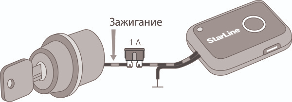
Immobilizer Connection
Power Connection
The GND wire of the blocking module must be connected to the vehicle body or a conductor reliably connected to the body. This wire should be connected first during installation.
Ensure the module receives power via the BAT terminal, and this power should not be interrupted under any circumstances. Ignoring this requirement can lead to immobilizer malfunctions, such as unintended activation of the anti-theft function, which can cause sudden changes in engine performance. The IGN wire must have a +12V potential when the ignition is on and the engine is running.
When connecting the BAT wire, remember that the maximum current consumption can reach 30A (during the pulse control of the locks).
Engine blocking circuit connection
NO, NC and COM wires are connected to the circuit that needs to be blocked.
Both normally closed (COM and NC) and normally open (COM and NO) contacts can be used for blocking.
The relay activates only at the moment of engine blocking. Turning off the ignition does not trigger the relay.
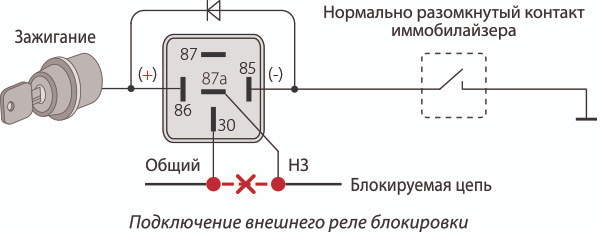
The switching current should not exceed 10A continuously and no more than 20A for up to 1 minute (when switching circuits without an inductive load component). The size of the blocking module allows it to be installed close to the blocking point. Monitor the length and cross-section of the wires used for switching, as the switched current can be significant. If the current in the blocked circuit exceeds 10A, use an additional external relay.
Lock Control Output Connection
UNLOCK and LOCK outputs are for controlling the hood lock or central door lock. They are designed with a power circuit (maximum output current 20A), so additional power modules are not required for lock control. Lock control can be implemented either through two-wire drive systems or by direct connection to the central locking system with negative control.
Connect the INPUT wire to the corresponding limit switch to allow the system to monitor the status of the doors or hood. If the door or hood is open, the lock will not be engaged. This wire should have a ground (–) when the hood (or doors) is open.
| Lock control method | Output | "Open" pulse | "Close" pulse | |
|---|---|---|---|---|
| Control of hood (disabled “Hands free” mode) | Two-wire locking system actuators | UNLOCK |
+ |
– |
| LOCK | – | + | ||
|
Control of doors (enabled “Hands free” mode) only for i95 LUX, i95
|
Central locking system with negative control | UNLOCK |
– |
break |
| LOCK | break | – | ||
| Two-wire locking system actuators | UNLOCK |
+ |
– |
|
| LOCK | – | + | ||
Before connecting the power outputs for the lock, choose the appropriate control scheme.
I95, I95 LUX
When connecting the immobilizer control outputs directly to the central door lock control unit, you must choose a central locking system with negative control. Failure to follow this rule can damage the equipment.
After connecting, be sure to check the locking and unlocking algorithm of the central locking system (CLS) with both the immobilizer and the vehicle key. In rare cases, incorrect CLS operation may occur due to the specific features of the vehicle's standard circuits. In such cases, use an additional external relay with dry contacts to connect to the CLS control inputs.
If a malfunction occurs in the lock control circuit (e.g., short circuit or overheating) when a pulse is issued to lock or unlock, there will be 2 short beeps. Fix the malfunction before using the system.
Connecting the buzzer (i95 ECO, i95)
Connect the OUTPUT wire to the negative (–) terminal of the buzzer, and the positive (+) terminal to the BAT wire of the blocking module (+12V circuit). A LED can be connected in parallel to the buzzer through a resistor with a resistance of 1-2 kΩ.
Place the buzzer so its signals are clearly audible from the driver's seat.
WARNING: Do not place the buzzer close to the blocking module, as this can trigger the motion sensor when sound signals are emitted.
Connecting the status output (i95 LUX)
The "status" OUTPUT allows the immobilizer to work with external devices (alarm system, monitoring system, etc.) to monitor the presence of the vehicle owner. The output works as follows:
- High-impedance state (open circuit) if the tag is distant or absent (signal level of the tag is below the set proximity threshold).
- Low potential (–) if the tag is near the vehicle (signal level of the tag exceeds the set proximity threshold).
Connecting the Flexible Channel
The flexible channel (EXT) can be connected to one of the following inputs (outputs):
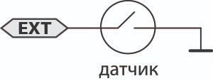
- Positive Brake Pedal Input: Used to implement brake pedal interrogation before starting the anti-hijack algorithm. Pressing the brake pedal is detected by the presence of +12V potential at the input.
- Positive Limit Switch Input: Used to determine the status of the doors or hood. This is for vehicles with +12V potential at the limit switch when the hood (doors) are open.
- Negative Touch Sensor Input (i95, i95 LUX): Connects to a touch sensor (installed separately). In "Hands-Free" mode, if the tag is in the blocking module’s action zone, the central lock will only unlock with a signal from the touch sensor. The door will lock with a long touch on the sensor (more than 3 seconds) or when the tag moves away.
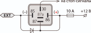
- Brake Light Output: Low-current (400 mA) negative output. Used to alert others of an impending vehicle stop before starting the engine blocking algorithm. Warning signals in the cabin are duplicated by flashing the vehicle's brake lights.
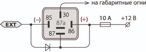
- Parking Light Output: Low-current (400 mA) negative output. Used for light indication of automatic lock and unlock. One signal is sent to the parking lights when issuing the "lock" pulse. Two signals are sent to the parking lights simultaneously with the "unlock" pulse.
- Status Output: Used as the default channel setting. Designed to monitor the presence of the tag near the vehicle. The output operation algorithm fully corresponds to the description in the "Connecting the Status Output" section. For the i95 ECO immobilizer, the status output works only when the ignition is on.
Before connecting the EXT wire, configure the channel according to the chosen connection method.
To attach the indicator module, use the double-sided tape included in the kit. If necessary, the power cord can be hidden in the cutout at the bottom of the indicator module housing.
Connecting the Indicator Module
- Use the double-sided tape included in the kit to attach the indicator module to the selected surface.
- Ensure Ignition is Off.
- Connect the black wire of the blocking module to the vehicle’s ground.
- Connect the black wire with a gray stripe to the standard wire that has +12V only when the ignition is on. The voltage should not disappear when the starter is engaged.


