
Installation
SIM card installation
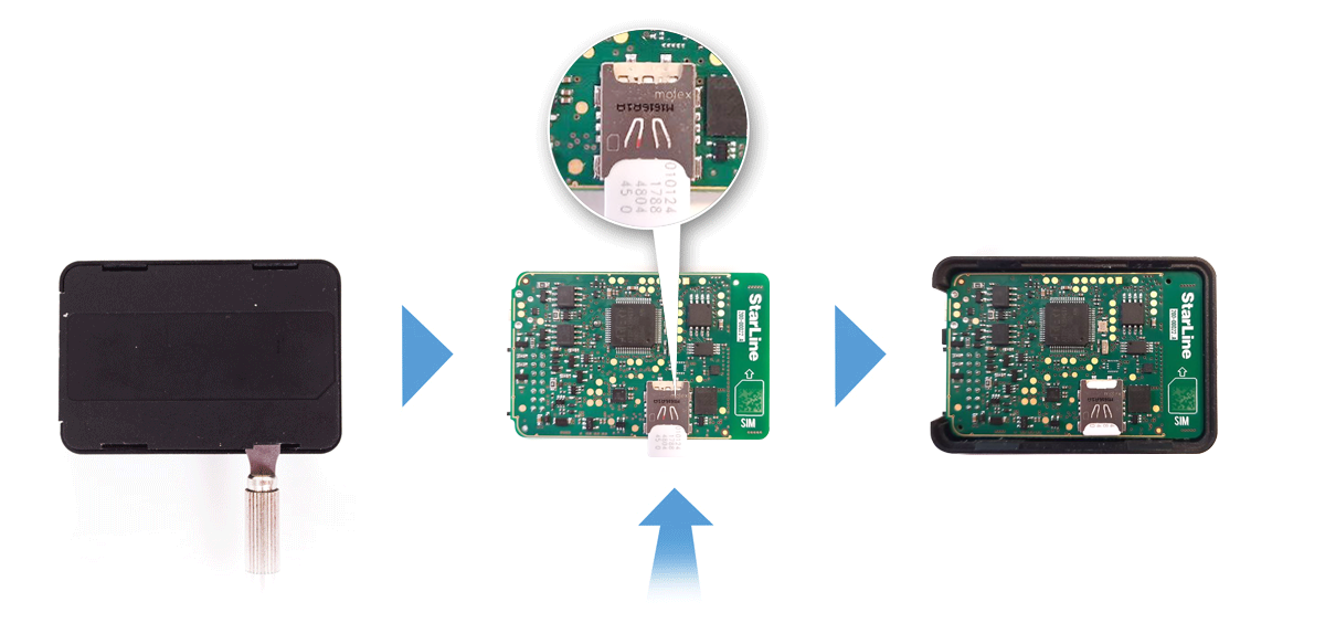
Open main unit housing with a flat metal item. Insert SIM card into the slot on the circuit board.
Put the board back in the case. Close the case lid.
Tracker placement recommendations
The system main unit must be placed so that its cover is pointing towards the sky (StarLine logo side up).
Also the unit must not be obscured by metal objects and coatings.
The satellites signal well passes through glass, plastics, decorative door paneling, but does not pass through a metal body, metallized tinting and other metal objects.
Connection diagram

Black wire - connection to vehicle's ground (-).
This connection must be done first.
Recommend to crimp the wire into the ring terminal and fix it with one of the vehicle's factory ground bolt (screw).
Red wire — connection to vehicle's power feed 12 or 24 V.
The wire must be connected to one of the permanently powered contact or wire of 0.5 mm2 thickness at least, or directly to the vehicle's main battery terminal through the supplied 3A protective fuse. Typical connection points: fuse, relay box or body control module (BCM) power supply, ignition switch.
Green wire — universal output / input No 1.
Activated by SMS command K1+.
Can be used as an engine kill control, universal output for the other circuits (dashcam, buzzer, siren, PTS button), or input for an auxiliary sensor.
For example, set the output function to Engine blocking in Channel settings and select NO (normally open) or NC (normally closed) connection type in Engine blocking settings of StarLine Master program. Break one of an engine control circuits with automotive relay and connect this output to the control contact.
Blue wire — universal output No 2.
Activated by SMS command K2+.
Can be used as an engine kill control, universal output for the other circuits (dashcam, buzzer, PTS button).
Yellow wire — can be used for ignition or auxiliary sensor control.
White-black wire — can be used as StarLine data bus to connect the other optional StarLine extention devices or as universal output for the other circuits control (dashcam, buzzer, siren, PTS button)
The NC (normally closed) engine kill connection type is set by default.


Brown, brown-white, orange and orange-white wires — digital CAN bus interfaces. Find recommended connection points and diagrams for your vehicle at can.starline.bz.
The system operation is configured with the help of StarLine Master program.